I
Product Components
Launch Monitor Main Unit 1 piece, including bracket
Power Adapter 1 piece
Clubhead Stickers 5 sheets
Calibration Plate 1 piece
Conversion Connector 1 piece
Screw Washer 1 pack
Component specifications No. Name Quantity Unit Specification
1 Launch Monitor Main Unit (including bracket) 1 Piece \ 2 Power Adapter 1 Piece Input: 100-240VAC, 50/60Hz, 1.3A; Output: 24V-3.75A, 90W MAX 3 Clubhead Stickers 5 Sheets Each sticker diameter: outer 5mm, inner 2.5mm 4 Calibration Plate 1 Piece \ 5 Conversion Connector 1 Piece 3-hole to DC connector 6 Screw Washer 1 Pack \
II / 1
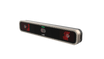
Launch Monitor Introduction
Sensor Type Overhead-mounted, triple high-speed camera launch monitor
Product Name GOLFJOY Rigel 3 Pro
II / 2
Launch Monitor Basic Parameters
Installation Overhead Front-mounted
Install Height 2.75–3.1 m 2.91–3.1 m with 3D Stance Hitting Mat
TEE Distance 110 cm
Calibration Automatic No camera/focus/infrared light adjustment
Supported Balls Any ball Including pure white balls
Hitting Zone 60 × 60 mm
Ball Data 7 metrics
Club Data 11 metrics
Full basic parameters
Installation Method Overhead, front-mounted Installation Height 2.75–3.1 meters (without 3D Stance Hitting Mat); 2.91–3.1 meters (with 3D Stance Hitting Mat) TEE Distance 110 cm Calibration Method No need for camera/focus/infrared light adjustments, automatic calibration Supported Balls Any ball (including pure white balls) Rough and Bunker Supported 3D Stance Hitting Mat Supported Weight 4.95 kg; 5.95 kg (with wall bracket) Dimensions 75.6 cm (Length) × 16 cm (Width) × 7/12.7 cm (Thickness) Number of Lenses 3 Illumination 40 LEDs × 2 sets Hitting Zone 60 mm × 60mm Ball Data 7 metrics: Ball speed, launch angle, launch direction, backspin, side spin, spin axis, spin rate. Club Data 11 metrics: Club speed, attack angle, club path, face angle, face to path, impact location, dynamic loft, spin loft, closure rate, low point, smash factor Trajector Data 24 metrics Power Input: 100-240VAC/50-60 Hz 2.5A; Output: 24V, 3.75A, 90W Material Aluminum alloy + TPU Color Gray with black Connection Method Ethernet Applicable Environment Indoor Operating Temperature -10°C to 40°C (Power-on test at -10°C) Altitude Below 3000 meters Humidity 20% to 70% Storage Temperature -20°C to 80°C
II / 3
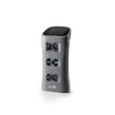
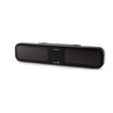
External Interfaces / Buttons
Power Button
Power Port
Ethernet Port
II / 3
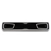
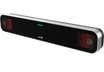
Status Indicator Lights
During Power-Up: Blue light flashes.
Power-Up Complete: Blue light stays on.
Connected to Client/App: Blue light stays on.
Ball Detected: Green light stays on.
No Club Data Zone, Ball Detected: White light stays on.
Fault Alarm: Red light flashes.
II / 4
Function Description
One-click calibration No lens, focus, infrared light board adjustments, or configurations.
Triple high-speed cameras Wide field of view with 60×60 cm sensor detection area.
3D Stance / Rough / Bunker Compatible with 3D Stance Hitting Mat, rough and bunker grass.
Any ball Supports any ball, including pure white balls.
Clubhead replay Supports clubhead trajectory replay and frame-by-frame impact analysis.
Left / Right handed users Supports both left and right-handed users.
Sleep mode Default 15 minutes. Move or cover the ball to wake the launch monitor.
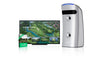
WiFi Works with GOLFJOY PRO and GOLFJOY SPACE apps.
Certification Certified by CE, FCC, RoHS, and other international certifications.
III / 1
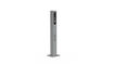
External Calibration · Installation Positioning
Prepare the tools shown below. Install the launch monitor as shown in the diagram.
Mounting Clip-on Mount the base, slide into the clip, secure with safety screws.
Direction Front-mounted
Install Height 2.75–3.1 m
TEE Distance 110 cm
Note: For 3D Stance Hitting Mat compatibility, the installation height is 2.91 to 3.1 meters.
III / 2
Calibration
1 Automatic Network Setup Open GolfjoyInstallHelper.exe. Select Rigel 3 Pro and click Next.
2 Place Calibration Plate Place the plate in the green box. Cover the TEE and point the arrow toward the hitting direction.
3 Mark the Area Mark only the left area. Skip rough or bunker if they are not configured.
III / 3
Clubhead Sticker Method
Purpose Clubhead data Required for high-precision clubhead data.
Method Five-point Use the provided circular stickers.
Detection Area Yellow area Hit balls within the designated yellow detection area.
Placement Small error accepted A small margin of error is acceptable.
For Wood Clubs
Align the 2nd, 4th, and sweet spot horizontally.
Place the 2nd point 5mm from the left edge and the 4th point 5mm from the right edge.
Keep the line from 2nd to 1st parallel to the centerline.
Place the 5th point on the centerline, 5mm from the top.
Place the 3rd point on the bottom score line, close to the left edge.
For Iron Clubs
Align the 2nd, 4th, and sweet spot horizontally.
Place the 2nd point at the left edge and the 4th point at the right edge.
Place the 1st point on the left edge of the second score line from the top.
Place the 3rd point on the left edge of the second score line from the bottom.
Place the 5th point on the centerline, 5mm from the top.
III / 4
Ball Test
Test result Once the software detects the ball, hit and check whether the data and playback video are available.
Ball test interface
III / 5
Area Verification
1 TEE Area Verification Place the ball on the TEE. The client will prompt verification.
2 Rough Area Verification Place the ball on the rough area. The client will prompt verification.
3 Bunker Area Verification Place the ball on the bunker area. The client will prompt verification.